 English
 中文简体
中文简体 Español
 svenska


The spindle component of the CNC milling machine is the main component that affects the machining accuracy of the machine tool. Its rotation accuracy affects the machining accuracy of the workpiece; its power and rotation speed affect the processing efficiency; its automatic speed change, exact stop and tool change affect the degree of automation of the machine tool. Therefore, it is required that the main shaft components should have high rotation accuracy, rigidity, vibration resistance, wear resistance and low temperature rise compatible with the working performance of the machine tool. In terms of structure, problems such as the clamping of the tool and the workpiece, the configuration of the bearing, the adjustment of the bearing clearance, and the lubrication and sealing must be well solved.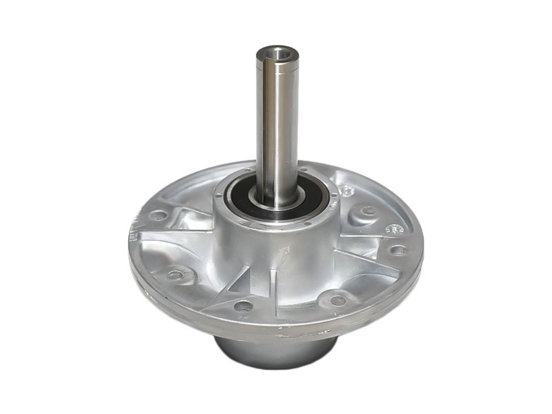
The spindle should adopt different spindle bearings according to the specifications and accuracy of the CNC milling machine. Generally, the main shaft components of small and medium-sized CNC milling machines use groups of high-precision rolling bearings, Precision Spindle Assembly use hydrostatic bearings, high-precision CNC milling machines use gas hydrostatic bearings, and spindles with a speed of 20000r/min use magnetic bearings or nitriding. Ceramic ball bearings made of silicon.
The sealing structure of the front support of the spindle is shown as the sealing structure of the front support of the horizontal machining center, which uses a double-layer small gap sealing device. The front end of the main shaft is turned with two sets of serrated oil protection grooves, grooves and oil drain holes are opened on the flanges 4 and 5, when the oil sprayed into the bearing 2 flows out, it is blocked by the inner wall of the flange 4 and passes through the lower part. The oil drain hole 9 and the oil return oblique hole 8 on the sleeve 3 flow back to the oil tank. When a small amount of oil flows out along the main shaft 6, the main shaft oil protection groove is thrown into the groove of the flange 4 under the action of centrifugal force. The oil return oblique hole 8 flows back to the oil tank again, achieving the purpose of preventing the leakage of lubricating medium.
When external cutting fluid, chips, dust, etc. enter along the gap between the main shaft 6 and the flange 5, they can be discharged from the drain hole 7 through the groove of the flange 5. A small amount of cutting fluid, chips and dust enter the front serration groove, and are still thrown into the groove of the flange 5 under the action of the centrifugal force of the high-speed rotation of the main shaft 6, and discharged from the drain hole 7 to achieve the end seal of the main shaft. the goal of.
To make the gap sealing structure have good sealing and anti-leakage performance within a certain pressure and temperature range, it is necessary to ensure that the matching gap between the flanges 4 and 5 and the spindle and bearing end faces meet the following conditions.


