 English
 中文简体
中文简体 Español
 svenska


Content
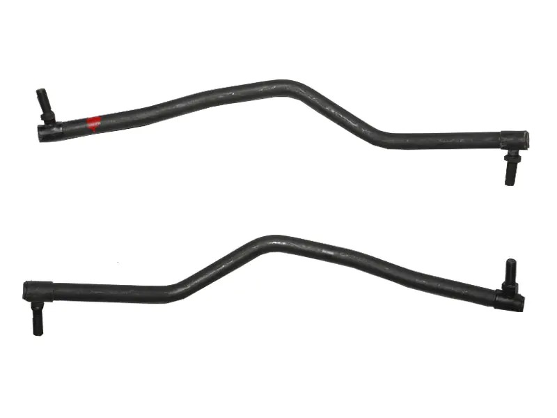
What Are Steering Drag Links?
Steering drag links are solid or tubular rods that transfer rotational motion from the steering gear output shaft to the steering knuckle arm, causing the front wheels to pivot left or right. In recirculating-ball and worm-and-sector steering systems — found on the majority of trucks, SUVs, heavy commercial vehicles, and older passenger cars — the drag link is the primary mechanical connection between the steering box pitman arm and the first steered wheel. Without it, turning the steering wheel produces no directional change at the road surface.
The drag link is distinct from the tie rod: tie rods link the two front wheels together to maintain parallel tracking, while the drag link links the steering box to the wheel assembly. On solid front axle vehicles, a single drag link typically runs from the pitman arm to the right-side steering knuckle arm, with a tie rod then connecting both knuckles. Understanding this layout is essential when diagnosing steering looseness, bump steer, or alignment drift.
How Drag Links Work in the Steering System
When the driver turns the steering wheel, the steering gear converts rotary input into lateral arc motion at the pitman arm. The pitman arm sweeps through an arc, and the drag link — attached at one end to the pitman arm ball stud and at the other to the knuckle arm ball stud — translates that arc into a near-linear push or pull force on the knuckle arm. The knuckle arm rotates the spindle on a kingpin or ball joint, turning the wheel.
Both ends of the drag link terminate in ball-and-socket joints, allowing multi-axis articulation to accommodate suspension travel, body roll, and axle wind-up without binding. The joint at the pitman arm end is typically non-adjustable and pre-loaded at the factory; the joint at the knuckle arm end often incorporates a tapered threaded adjuster sleeve that allows the overall rod length to be set during front-end alignment to achieve the specified caster angle and steering geometry.
Drag Link vs. Tie Rod: Key Functional Differences
| Parameter | Drag Link | Tie Rod |
|---|---|---|
| Primary function | Transmits steering input from box to knuckle | Synchronizes both front wheels |
| Connected to | Pitman arm → steering knuckle arm | Left knuckle ↔ right knuckle |
| Load type | Compression and tension (steering force) | Tension (toe alignment) |
| Alignment adjustment | Caster / steering center | Toe-in / toe-out |
| Typical failure symptom | Wandering, loose steering feel | Uneven tire wear, pulling to one side |
Construction and Materials
A drag link must resist both compressive buckling loads (when pushing the knuckle during turns) and tensile pulling loads (when pulling it back), while surviving constant vibration, road shock, and corrosive environments. Material and cross-section selection directly determines service life and safe load capacity.
Rod Body
- Solid steel rod — Used on light-duty and passenger vehicles. Carbon steel (typically SAE 1040 or 1045) is cold-drawn to close tolerances, providing good compressive strength in a compact cross-section. Simple to manufacture and cost-effective for loads up to approximately 20 kN.
- Seamless steel tube — Standard on medium and heavy commercial vehicles. Hollow section achieves a superior strength-to-weight ratio compared to solid rod at equivalent diameter — critical on vehicles where unsprung weight directly affects ride quality and suspension geometry. DOM (Drawn Over Mandrel) tubing is preferred for its consistent wall thickness and internal surface finish.
- High-strength alloy steel — Specified for heavy trucks, off-road equipment, and aftermarket performance applications. Chromoly (4130 or 4340) provides yield strength of 620–1,000 MPa, enabling thinner wall sections or higher load ratings without increased diameter.
- Forged ends — The ball joint housings at each end are typically forged rather than cast or machined from bar stock, as forging aligns the grain structure of the steel along the load path, significantly increasing fatigue life at the highest-stress region of the assembly.
Ball Joint Design and Pre-Load
The ball-and-socket joints at each end of the drag link are the most maintenance-sensitive components in the assembly. A correctly designed drag link end joint maintains a defined axial pre-load on the ball stud — enough to eliminate free play under normal driving loads, but not so tight as to increase steering effort or restrict articulation during full suspension travel.
Two pre-load designs dominate the market:
- Spring-loaded (self-adjusting) design — A coil spring behind the bearing seat continuously compensates for wear, maintaining pre-load throughout the service life. These joints tolerate higher wear rates before developing perceptible play and are standard on heavy trucks and off-road vehicles.
- Fixed pre-load design — A threaded plug sets pre-load at assembly. Simpler and lower cost, but pre-load decreases as the bearing seat wears, eventually resulting in a loose, clunking joint that requires replacement.
Bearing seat materials include sintered bronze, PTFE-impregnated nylon, and hardened steel depending on application. Grease-able designs with a Zerk fitting allow fresh grease to be injected during routine maintenance, flushing contamination and significantly extending joint life. Permanently lubricated (sealed) joints require no maintenance but cannot be serviced and must be replaced as a unit when worn.
Vehicles and Applications That Use Drag Links
Drag links are found wherever a recirculating-ball or worm-type steering gear drives a solid or beam front axle. This covers a substantial proportion of the global vehicle and equipment fleet:
- Heavy commercial trucks (Classes 6–8) — All major platforms including Freightliner, Kenworth, Peterbilt, Volvo, and DAF use drag link steering on both steer axles and pusher/tag axle configurations. A Class 8 tractor may carry two drag links — one from the steering box to the front axle, and a second relay rod linking front and rear steer axles on tandem-steer configurations.
- Full-size pickup trucks and body-on-frame SUVs — Ford F-250/F-350 Super Duty, Ram 2500/3500, Chevrolet Silverado HD, and Toyota Land Cruiser (solid axle variants) all use drag link steering systems. These are common platforms for aftermarket lift kits that require extended or corrected-geometry drag links to prevent bump steer.
- Off-highway construction and mining equipment — Motor graders, wheel loaders, and articulated dump trucks use heavy-gauge drag link assemblies rated for extreme shock and impact loads. These components are manufactured to significantly higher load specifications than highway vehicles.
- Agricultural tractors — Row-crop and utility tractors with mechanical front-wheel drive (MFWD) use drag links on the front axle, often with additional complexity due to the oscillating front axle design that must allow both steering and vertical articulation simultaneously.
- Military and specialist vehicles — High-mobility wheeled platforms use reinforced drag links with military-specification end joints rated for extreme off-road loads and wide temperature ranges (−50°C to +120°C operating range in some specifications).
Symptoms of a Worn or Failing Drag Link
Drag link wear is progressive and rarely causes sudden failure, but deteriorating components compromise vehicle control in ways that worsen proportionally with wear. Recognizing the early signs prevents expensive downstream damage and reduces safety risk.
- Steering wheel free play / excessive dead band — The most common symptom. A worn drag link end joint introduces slack that must be taken up before any wheel movement occurs. More than 30 mm of free play at the steering wheel rim is the typical commercial vehicle failure threshold under DOT annual inspection criteria.
- Steering wander — The vehicle requires constant minor steering corrections to maintain a straight line, particularly at highway speed. This indicates that road inputs are feeding back through the worn joint rather than being absorbed by the steering gear.
- Clunking or knocking over bumps — Impact loads cause a worn ball joint to travel through its free play range and contact the housing walls, producing a metallic knock from the front axle area. This is often mistakenly attributed to worn shock absorbers or loose spring U-bolts.
- Bump steer — The front wheels toe in or out as the suspension compresses, causing the vehicle to dart sideways over road undulations without any steering input. This can result from worn joints, a bent rod, or (on lifted vehicles) incorrect drag link geometry.
- Uneven or accelerated front tire wear — Worn drag link joints allow dynamic toe variation during driving, scrubbing tire tread in a pattern similar to misalignment but present even after a fresh alignment adjustment.
Inspection Procedure
The correct method for checking drag link joint condition requires a second person or a pry bar. With the front wheels on the ground and the vehicle stationary:
- Have an assistant turn the steering wheel left and right through approximately 30° while you observe the drag link joints from below with a flashlight.
- A good joint shows immediate, synchronized movement at both ends the instant the steering wheel moves. Any delay — even 1–2 mm of play visible at the joint — indicates wear requiring attention.
- With the steering held in a fixed position, attempt to move the drag link laterally by hand at each end. Any perceptible movement at the ball stud confirms excessive play.
- Inspect the rubber dust boot at each joint. A torn or missing boot allows water and road grit to contaminate the bearing seat, accelerating wear dramatically. Replace boots immediately if damaged, even if the joint itself still has acceptable play.
Replacement and Aftermarket Options
Drag link replacement requires selecting the correct length, end joint taper size, and thread specification for the vehicle. On adjustable designs, the new drag link must be set to the same effective length as the old one before installation — marked or measured on the original — and front-end alignment verified afterward to confirm caster and steering center have not shifted.
OEM vs. Aftermarket
- OEM replacement — Manufactured to the original vehicle specification. Preferred for commercial vehicles operating under fleet maintenance programs where documentation of OEM-equivalent parts is required for warranty or regulatory purposes. Typical cost premium of 30–60% over aftermarket alternatives.
- Direct-fit aftermarket — Parts manufactured to match OEM dimensions with equivalent or improved materials. Reputable suppliers (Moog, TRW, Delphi, Rare Parts) produce drag links to meet or exceed original specifications. These are the standard choice for independent workshops and fleet operators seeking cost efficiency without compromising quality.
- Heavy-duty / upgraded aftermarket — Thicker-wall tubing, larger-diameter ball joints, and chromoly construction for vehicles operating in demanding conditions: off-road use, lifted suspension, heavy towing, or high-mileage commercial operation. Extended service intervals of 2–3× OEM life are commonly claimed, particularly with grease-able end joints that allow ongoing maintenance.
- Custom-fabricated — Required when suspension lifts, axle swaps, or chassis modifications have altered the OEM steering geometry. A fabricated drag link is made to the exact length and joint angle needed for the modified geometry, eliminating the bump steer and bind that results from installing an OEM-length rod in an altered geometry.
Drag Link Flip and Correction Kits for Lifted Vehicles
Lifting a solid-axle vehicle changes the angle of the drag link relative to the ground, creating a condition known as drag link-induced bump steer: as the suspension cycles, the effective length of the drag link in the vertical plane changes, pulling the steering left or right. Two solutions exist:
- Pitman arm drop — A longer or dropped pitman arm repositions the drag link attachment point downward, returning the drag link to a near-horizontal angle and restoring OEM bump steer characteristics without changing the rod itself.
- Drag link flip — On vehicles where the knuckle arm points upward (as on some Dana 44 and Dana 60 axles), inverting the drag link to run below the axle centerline achieves a similar correction without a drop pitman arm, at the cost of reduced ground clearance at the rod.
Maintenance Intervals and Best Practices
Service life for drag link assemblies varies widely based on operating environment, joint type, and maintenance frequency. On paved-road vehicles with sealed joints, 80,000–160,000 km is a realistic service interval. Off-road, agricultural, or construction equipment may require joint inspection every 250–500 operating hours.
- Grease grease-able joints at every oil change — Use the correct grease specification for the application. Extreme-pressure (EP) lithium complex or moly-based greases are appropriate for most drag link end joints. Inject grease until it purges lightly from the boot lip — this confirms the joint is full and the old grease (with contamination) has been displaced.
- Inspect boot condition at every tire rotation — A torn boot on a sealed joint converts a maintenance-free design into a rapidly deteriorating one. Boot replacement on most drag link ends costs under USD 10 in parts; ignoring a torn boot typically results in joint failure within one to two seasons.
- Do not attempt to straighten a bent drag link — A bent rod has been plastically deformed. Straightening restores shape but introduces residual stress concentrations that significantly reduce fatigue life. A bent drag link should always be replaced.
- Replace in pairs when both ends show wear — Replacing only the more-worn end joint while leaving the other in service typically results in a return visit within one to two years. Most professional workshops replace the complete drag link assembly rather than individual end joints to avoid this.
- Verify torque to specification on all fasteners — Ball stud nuts on steering components use prevailing-torque or castellated/cotter pin designs for a reason. Never substitute with a standard hex nut, and always install a new cotter pin — never reuse the original. Under-torqued ball studs are a known cause of catastrophic joint separation.


