English
 中文简体
中文简体 Español
 svenska



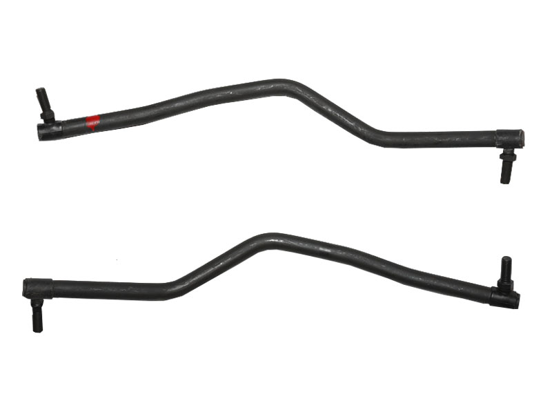
A steering drag link is the rigid connecting rod in a steering linkage system that transmits steering force from the pitman arm on the steering box to the steering arm on the front axle. In simple terms, it converts the rotary motion of the steering gear into the linear push‑and‑pull that turns the front wheels. Without a properly functioning drag link, the driver’s input at the steering wheel would never reach the wheels, and directional control would be lost completely.
In most commercial trucks, buses, and heavy‑duty vehicles that use recirculating‑ball steering gears, the drag link is a critical structural component. It absorbs shock loads from rough terrain and must withstand both tensile and compressive forces that can exceed 15,000 Newtons in a loaded truck. Understanding what is a steering drag link and its exact steering drag link function is essential for anyone responsible for vehicle maintenance or performance tuning.
Content
How Does a Drag Link Work?
The drag link works by forming a mechanical bridge between two pivot points that are typically misaligned — one on the steering gearbox side and one on the axle side. When the driver turns the steering wheel, the steering gear rotates the pitman arm through an arc. This pitman arm pushes or pulls the drag link, which in turn forces the steering arm on the steering knuckle to rotate. That rotation is what swivels the wheel assembly.
The ends of a drag link are fitted with joints — usually ball‑and‑socket joints or tapered stud assemblies — that allow the rod to move in multiple planes as the suspension articulates. A typical steering drag link operates at angles of up to 25 degrees from the horizontal during full suspension travel, and the joints must accommodate this without binding. To understand how does a drag link work practically, consider a truck driving over an uneven surface: the axle moves up and down, the steering box remains fixed on the chassis, and the drag link pivots at both ends while still delivering steering inputs accurately. Any looseness in these joints introduces a delay known as free play, which can increase steering wheel slack to 10–15 degrees before the vehicle responds — a clear sign that the drag link or its associated steering system components are worn.
The Steering Linkage System Explained
To fully appreciate the drag link in steering system architecture, it helps to see the whole steering linkage system explained. In a typical recirculating‑ball steering setup found on heavy trucks, the system includes the following core steering system components:
- Steering gearbox: Converts rotation from the steering column into a powerful arc motion at the pitman arm.
- Pitman arm: The lever attached to the sector shaft of the gearbox, directly driving the drag link.
- Drag link: Connects the pitman arm to the steering arm on the knuckle, transferring the lateral force.
- Steering arm: Mounted on the steering knuckle, receives the drag link input and rotates the knuckle.
- Tie rod (or tie rods): Connects the two steering knuckles together, synchronizing the left and right wheel angles. On many solid‑axle trucks, a single tie rod runs behind the axle, linking the two knuckle arms.
- Steering knuckles: The pivoting assemblies that carry the wheel hubs and brake components.
The drag link is the first physical link after the gearbox and carries the highest steering loads. In many truck configurations, the drag link operates ahead of or alongside the front axle, directly connecting the pitman arm to the left steering knuckle (in left‑hand‑drive vehicles). The right wheel is then moved through the tie rod. This arrangement makes the drag link a unique component — it is part of the force transfer path from the steering wheel to a single wheel, not just a synchronization bar. Consequently, any failure in a truck steering drag link means complete loss of steering to at least one wheel, making its design factor of safety typically set to 2.5:1 or higher.
Heavy-Duty and Truck Steering Drag Links
When we talk about a heavy duty steering drag link or a truck steering drag link, we are referring to components built to endure far higher forces than passenger car parts. These drag links are typically forged from medium‑carbon alloy steel (such as SAE 4140 or 1045) and heat‑treated to a hardness of around 30–38 HRC for a balance of toughness and wear resistance. The shaft diameter can range from 30 mm to 55 mm depending on the vehicle’s gross vehicle weight rating (GVWR).
Key differences between standard and heavy‑duty drag links include:
- Larger ball stud diameters: Heavy‑duty versions often use ball studs with diameters of 25–35 mm, compared to 18–22 mm in light trucks, to handle the clamping force and shock loads.
- Reinforced sockets: The joint housings are thicker and may include grease fittings for regular lubrication intervals, typically every 30,000 to 50,000 km.
- Double‑end adjustability: Many truck drag links feature threaded adjustment sleeves at both ends, allowing precise centering of the steering gear without disconnecting the link from the vehicle.
- Integrated dampers: Some heavy‑duty drag links incorporate a built‑in steering damper bracket or a shock‑absorbing element to reduce vibration feedback to the steering wheel.
For vocational vehicles like dump trucks, concrete mixers, and logging trucks, an heavy duty steering drag link is further protected by a formed metal guard or is manufactured with an oversized cross‑section in high‑stress areas. Field replacement intervals are not time‑based but condition‑based: any radial or axial play exceeding 0.5 mm at the ball joint, or visible bending of the rod, mandates immediate replacement. A bent drag link can alter toe geometry during suspension travel, causing rapid and uneven tire wear that can consume a set of front tires in as little as 15,000 km.
Front Axle Steering Components and the Drag Link’s Place
A comprehensive view of front axle steering components reveals that the drag link is just one piece in a carefully choreographed mechanical chain. The following table lists the primary components associated with a solid front axle steering system and their relationship to the drag link.
| Component | Function | Connection to Drag Link | Typical Material |
|---|---|---|---|
| Pitman Arm | Transmits sector shaft rotation | Attached to drag link via ball stud | Forged alloy steel |
| Steering Knuckle | Pivots the wheel hub | Receives drag link motion through steering arm | Ductile iron or forged steel |
| Tie Rod | Synchronizes left/right wheel steer angle | Indirect: its position is set by drag link via knuckle | Seamless steel tube with threaded ends |
| King Pin / Ball Joints | Allow knuckle rotation and load bearing | No direct connection, but wear affects drag link load | Case‑hardened steel and bronze bushing |
| Steering Damper | Absorbs road shock and vibrations | Often mounted directly to drag link | Hydraulic cylinder with rubber bushings |
| Steering Box | Multiplies driver effort hydraulically | Outputs to drag link through pitman arm | Cast iron housing, hardened steel gears |
In modern steering geometry, the drag link does not operate in isolation — it is influenced by the front axle’s caster angle, the position of the tie rod, and the Ackermann steering principle. When a steering drag link is adjusted, the technician must ensure that the steering gearbox is centered before setting the drag link length, otherwise the vehicle will have an unequal number of turns left and right, a condition that can compromise safety in emergency maneuvers. Most heavy‑duty service manuals specify that the drag link length must be set such that the steering wheel is perfectly centered when driving straight ahead, with a tolerance of no more than ±1 degree of steering wheel angle.
Maintaining and Diagnosing Steering Drag Link Issues
Proactive maintenance of the drag link is a cornerstone of vehicle safety. Inspection should be part of every chassis lubrication service. The most common failure modes are ball‑joint wear, bending, and cracking at the adjustment threads. A worn drag link ball joint typically produces a distinct clunking noise during steering wheel reversal and can be confirmed by having an assistant rock the steering wheel while an inspector places a hand on each joint to feel for play. Any detectable radial movement in a dry ball joint means it has reached the end of its service life.
Alignment technicians also pay close attention to the drag link when setting toe‑in. If the drag link is bent even slightly, the effective steering arm length changes, and the toe setting will be incorrect under dynamic conditions. In trucks that operate off‑road or on heavily rutted surfaces, drag link straightness should be checked every 20,000 km using a simple straight‑edge or dial indicator. The cost of a replacement truck steering drag link is modest — typically between $150 and $600 for the part — but the cost of a drag link failure on the road, in terms of potential property damage and injury, is incalculable. Regular inspection and timely replacement are the only responsible policies.